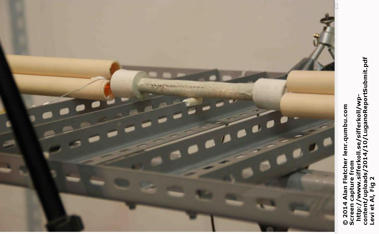
Fig 2 : Visible light, probably taken during the dummy run. No visible banding
Version 141014c Oct 27, 2014
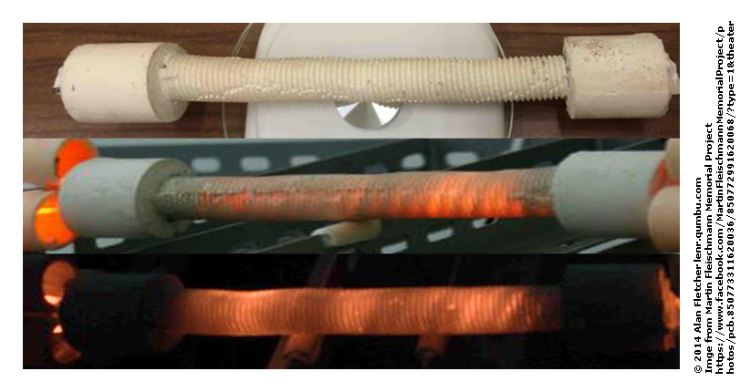
There is evidence of "banding" in the photos of the March 2014 hotcat test.
Lugano Paper, Levi et al
The test was run in three stages : (a) A dummy run, with resistive heating only, at a temperature callibrated as 450 C (b) an initial active run at 1260 C and (c) a higher-powered run at 1400 C
Fig 2 : Visible light, probably taken during the dummy run. No visible banding
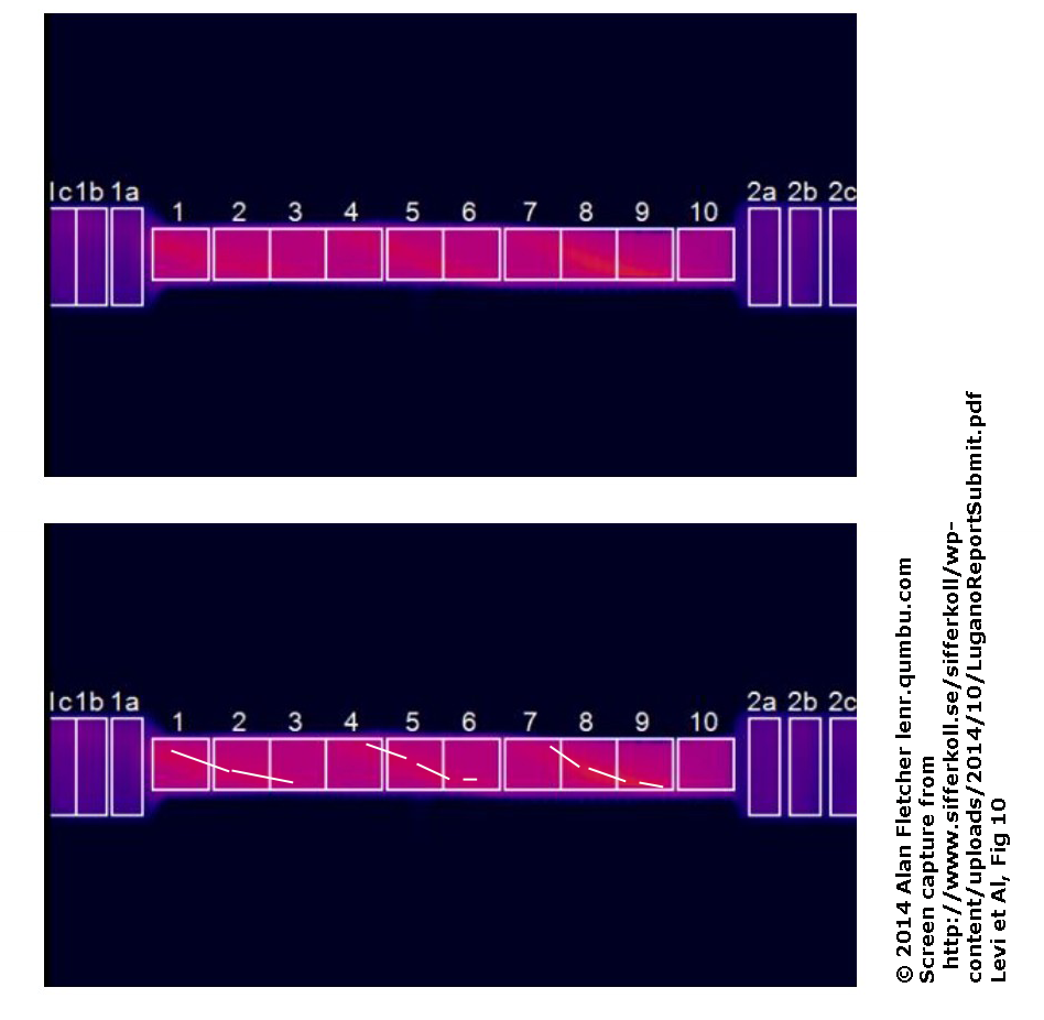
Fig 10 : Infra-red, during the dummy run. Possible banding on a coarse spiral
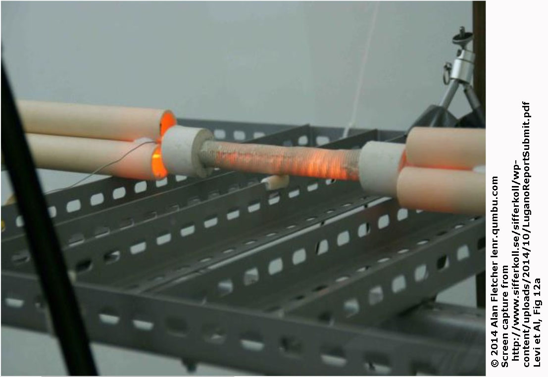
Fig 12a : Clear visible banding, but it is not known if this is from the low-power or high-power part of the test.
Also, there are no IR images of this stage.
An earlier test (Penon) clearly showed how the heater wires were mounted :
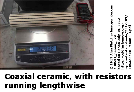
A ceramic insert held the wires, which were strung lengthwise.
The March 2013 Levi report showed an over-heated ecat, with clear longitudinal banding.
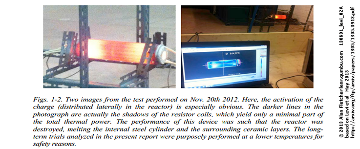
The described, but did not show, that the wires were held in a structure similar to Penon's.
Again, no pictures of the wire mount are shown in the 2014 test. The description just says the wires are in spirals.
Note : this is really an extension of my "Structure B" described below, based on new evidence from Bob Greenyer of the MFMP. I moved it up because I now think it's the most likely.
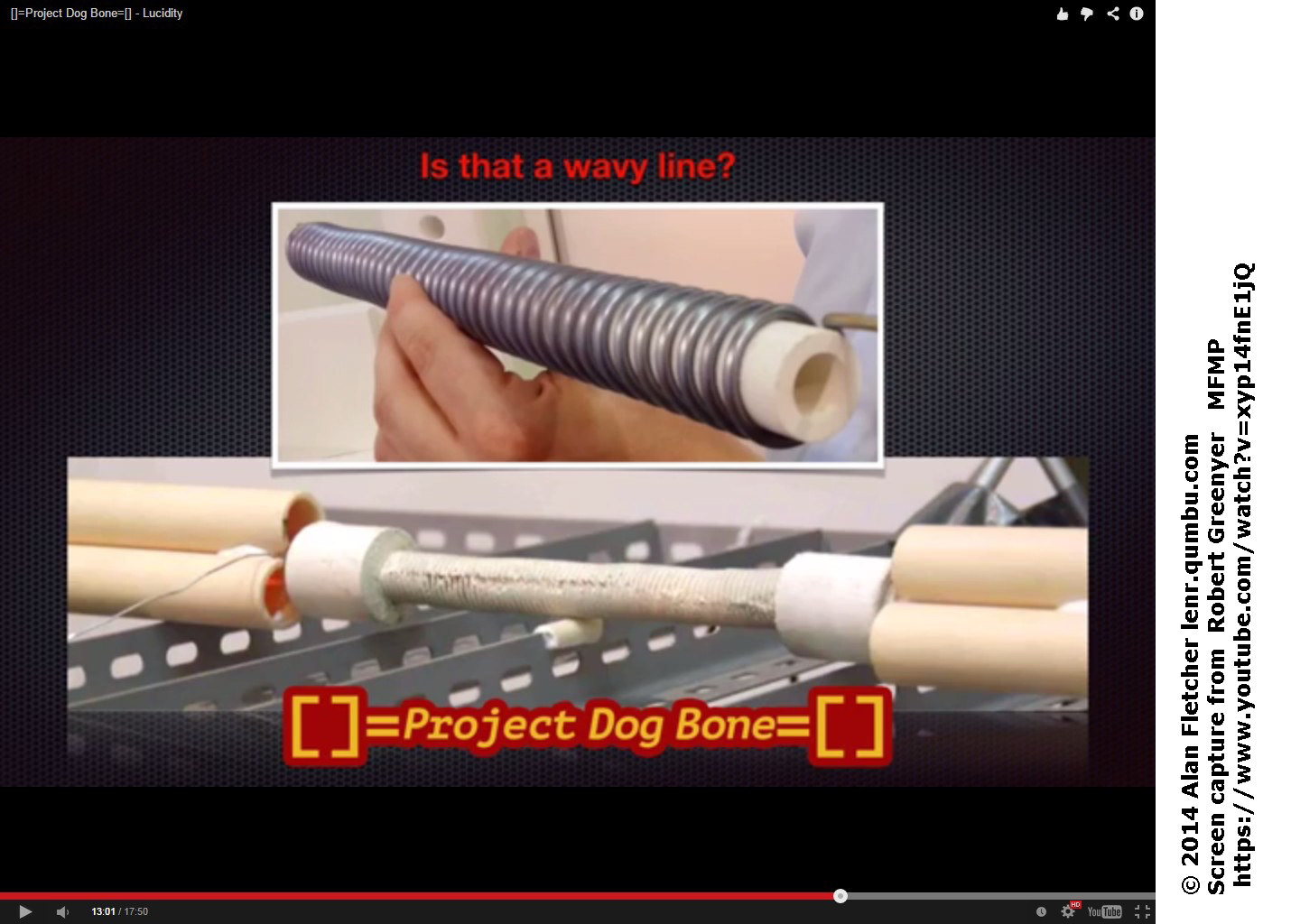
Greenyer notes the wavy structure of an electric heating element wound round a ceramic tube, and thinks that this explains the irregular structure of the Lugano hotcat: it's most likey alumina cement over an inner alumina cylinder.
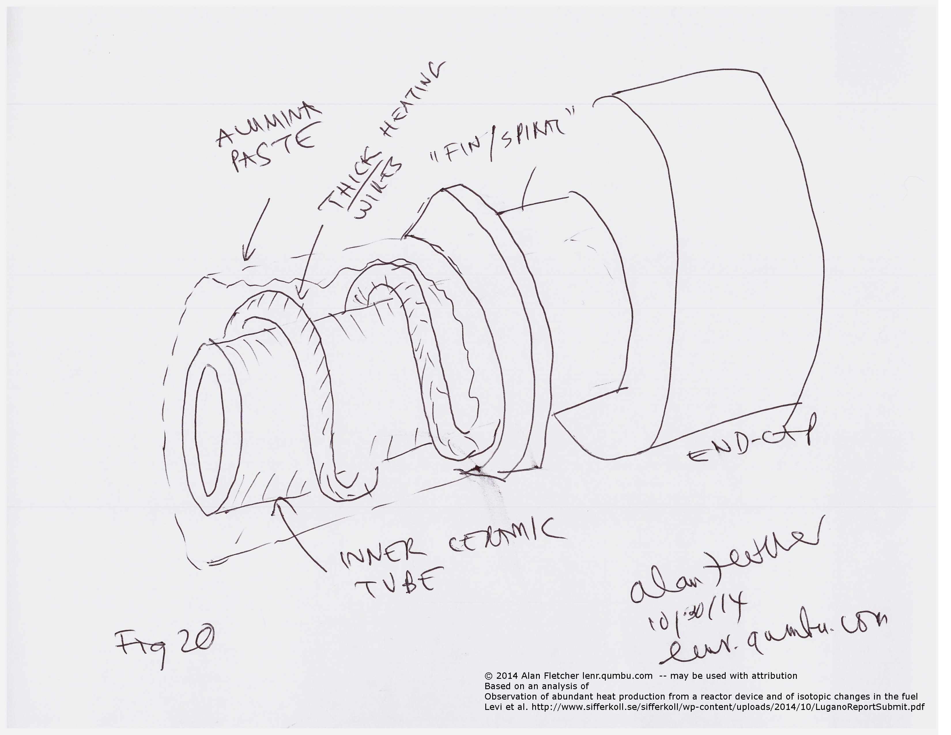
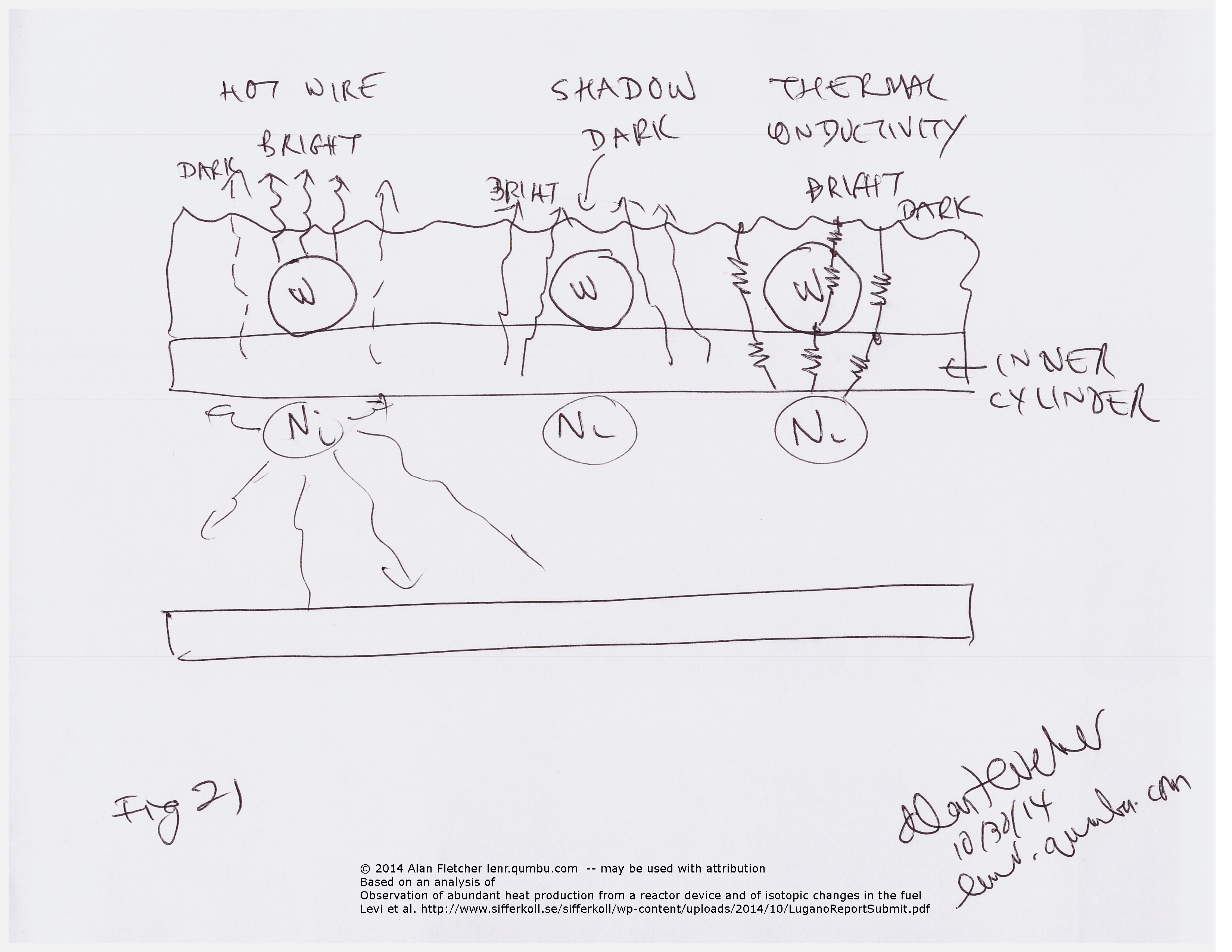
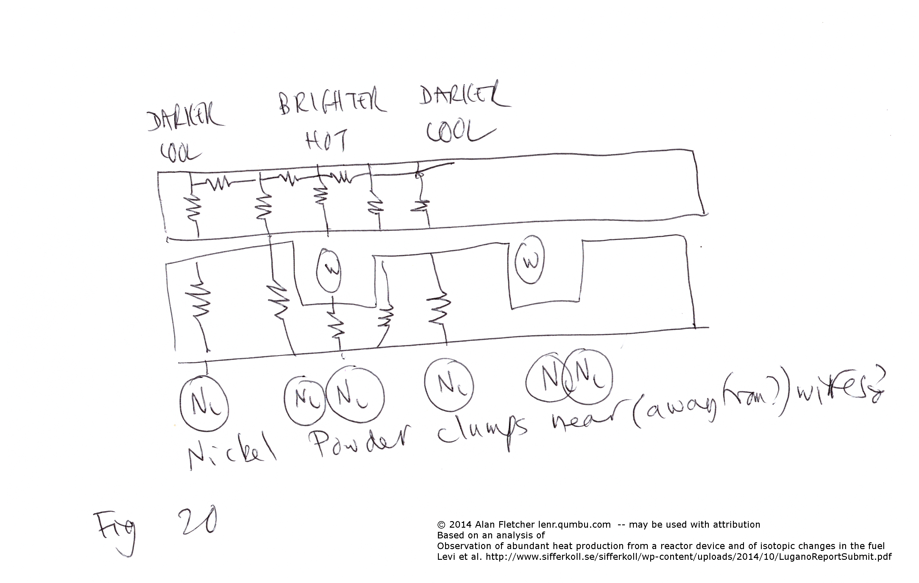
This gives three possible explanations for banding (left to right in fig 21):
If a ceramic support system were used it might look like this :
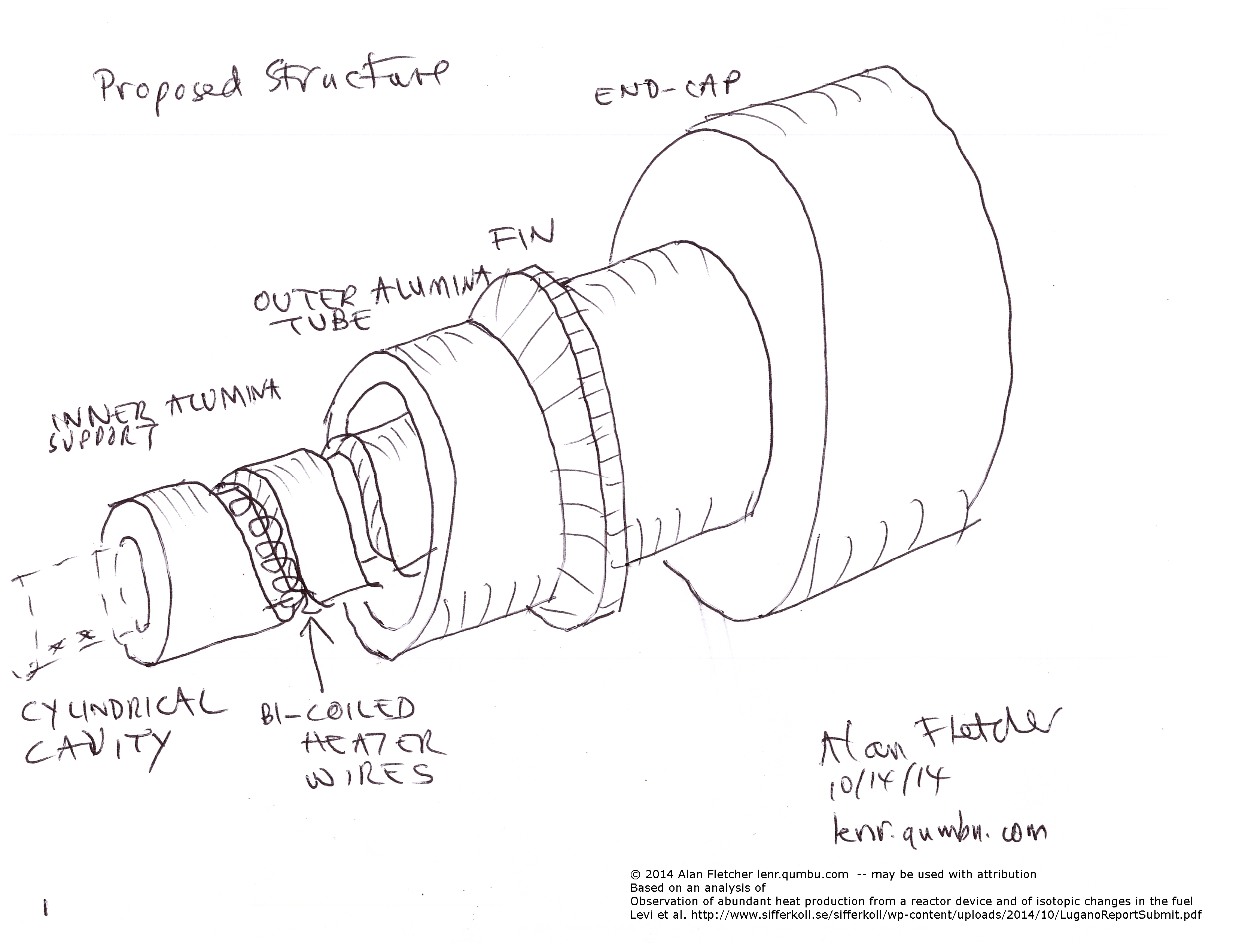
Fig 1
NOTE: I now believe that the 2014 hotcat is too small for this to work, but Bob Higgins of vortex says the alternative cannont be fabricated.
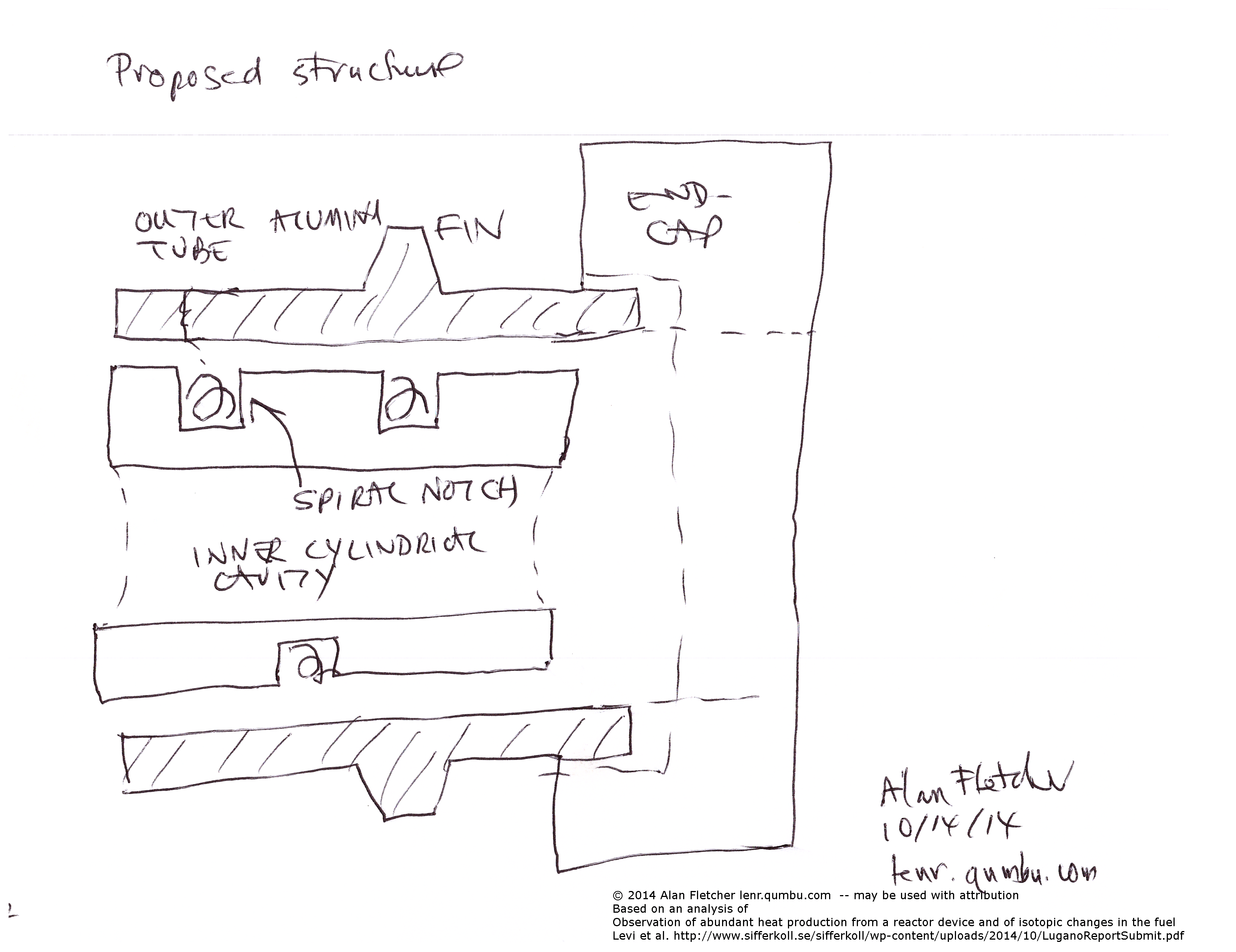
Fig 2 : side elevation.
Although the nickel particles are shown as being in the center of the tube, they could be heaped at the bottom, or distributed round the tube. However, this central cavity is likely to be in thermal equilibrium, so it's actually filled with black-body radiation. It is also unknown where the "thermalization" occurs : again, this could be in the particles, or on the walls of the cylinder.
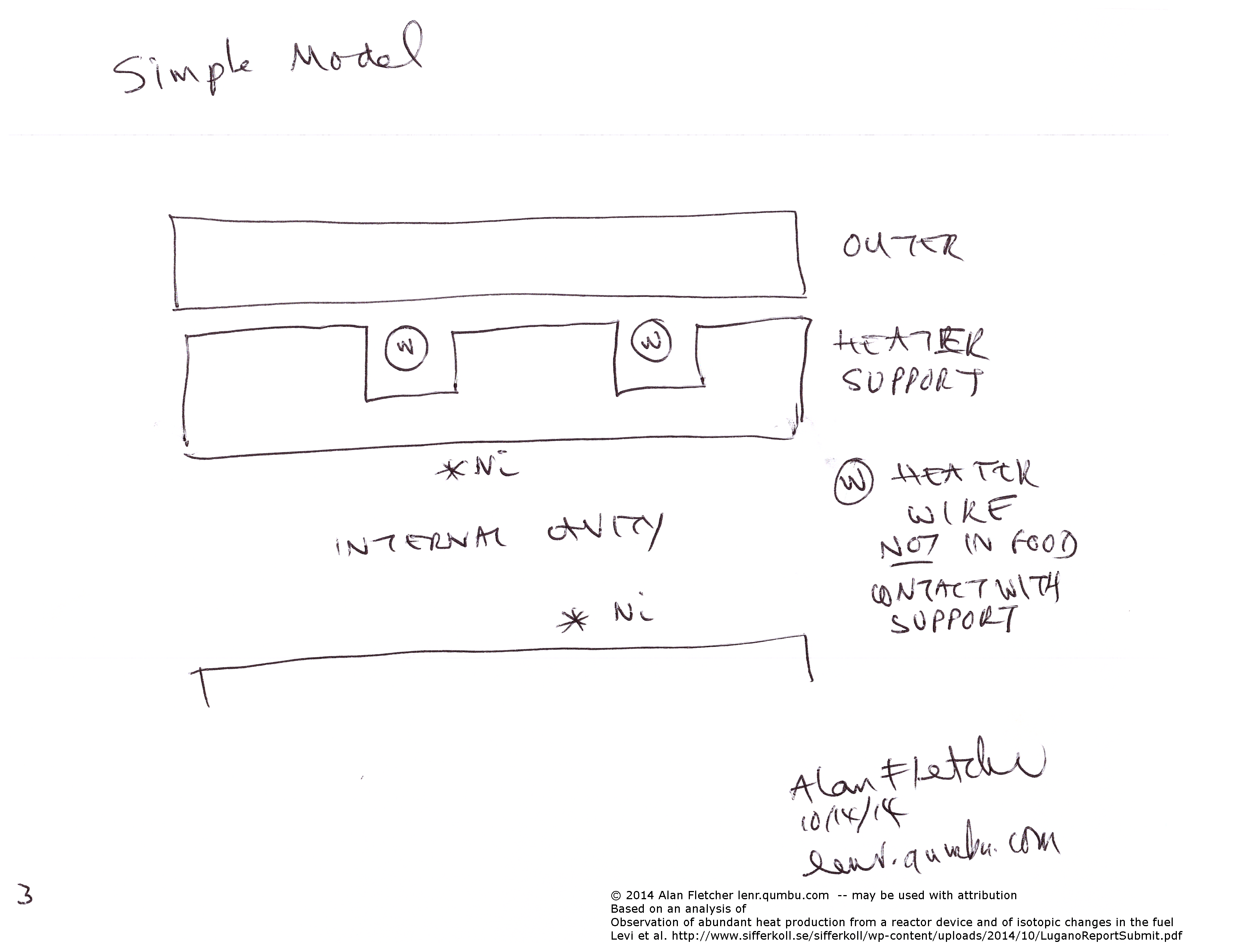
Fig 3 : Simplified model for thermal analysis. The fins are omitted.
One proposed reason is that the Alumina is transparent to visible radiation:
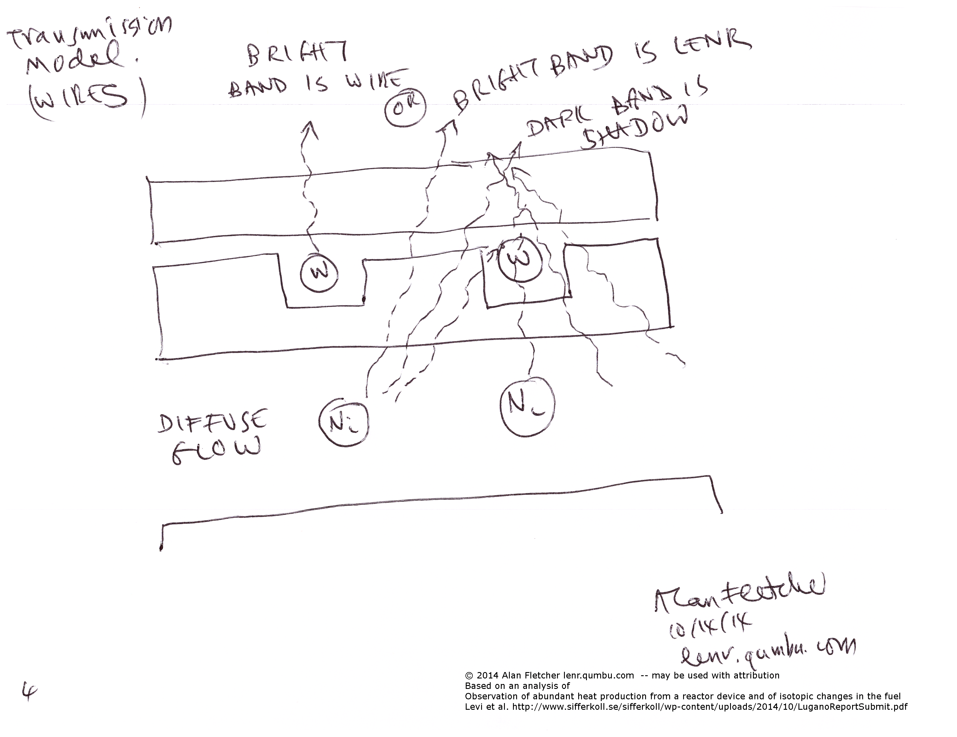
Fig 4 : Transmitted light model : bright wires or shadows of the wires
Here we have diffuse radiation from the center.
One possibility (shown on the left) is that the hot wire is visible through the tube, and that the darker segments represent the diffuse background glow.
The other possibility (suggested by the authors, and shown on the right) is that the wire is darker than the generated light, and that the dark bands represent the shadow of the wire against the bright background.
However, in this configuration I think that the background is too diffuse to cast a definite shadow.
An alternative structure will be described later.
However, another explanation of transmission is that the gaps provide a more transparent path for the light
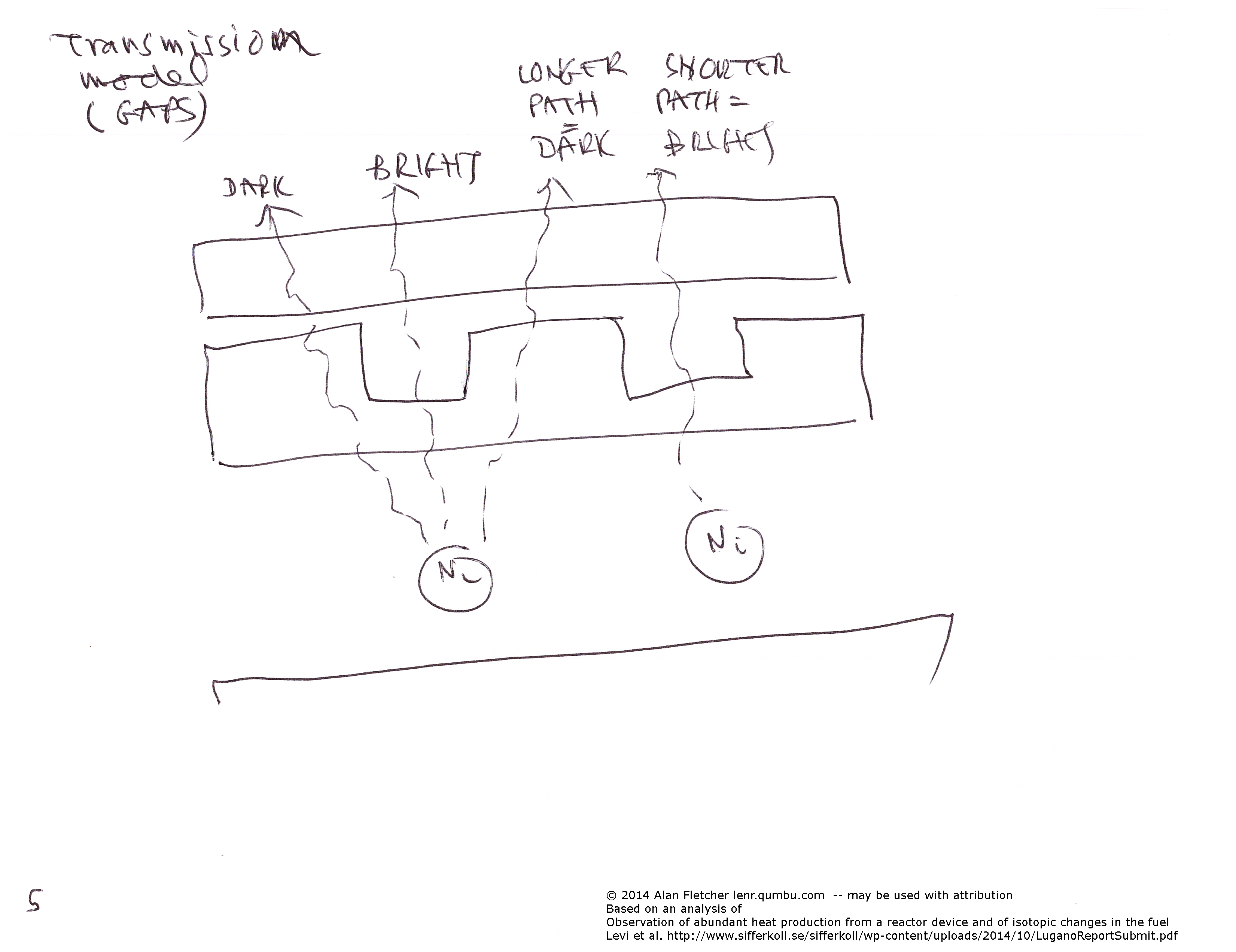
Fig 5 : Transmitted light model : there is simply less ceramic in the gaps, so these will show as brighter.
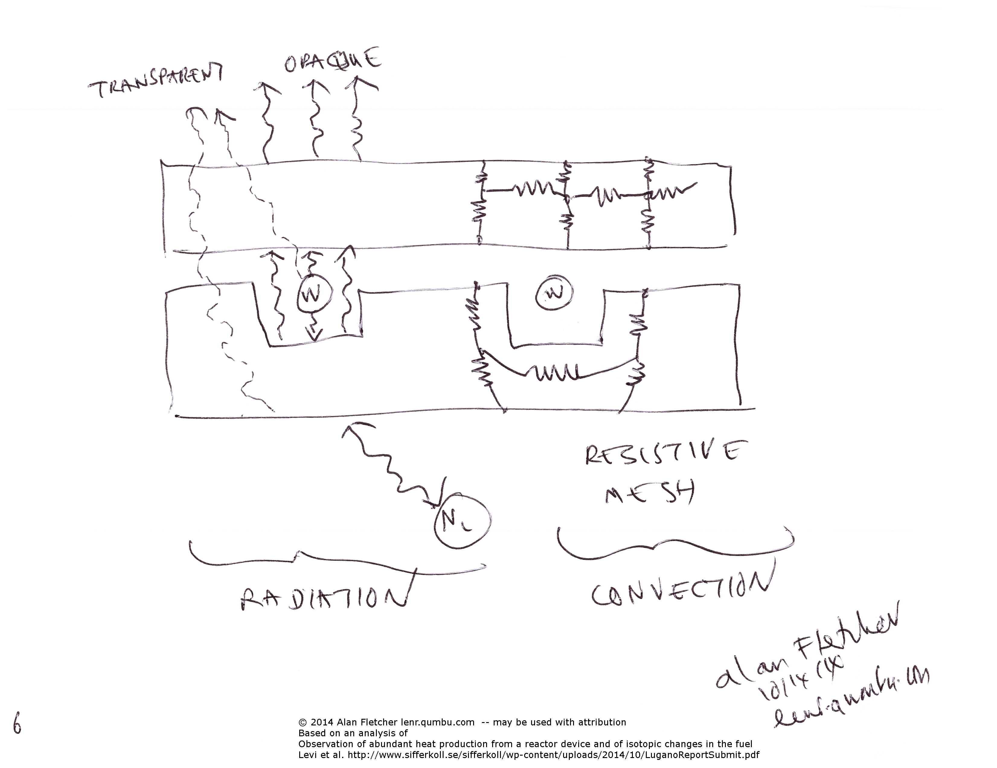
Fig 6: on the left we show the paths of radiation, and on the right we show the conductive paths. (Incorrectly labelled convection on the diagram).
If the ceramic is visually transparent then there may be direct paths, as before.
Black body radiation will fill both the inner cavity and the gap that holds the wires, which are presumed to be in poor thermal contact with the ceramic.
On the right we show the conductive paths, which can be modeled as a mesh of resistors.
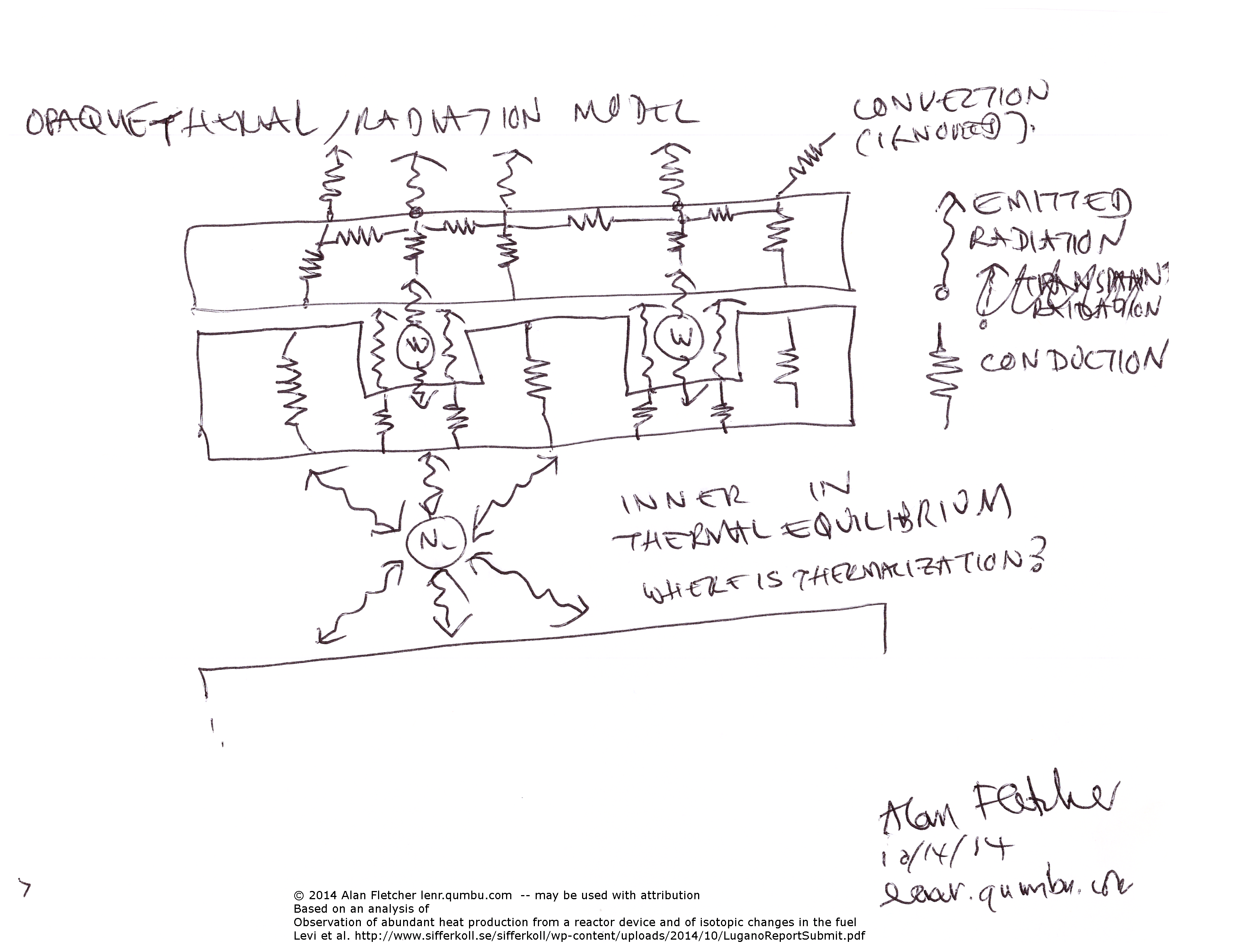
Fig 7: opaque radiative and conductive paths, omitting direct transmission.
This diagram also indicates that there is convection from the surface, but this is unlikely to effect the banding, so it can be ignored.
The thermal conductivity of Alumina is fairly low, so the entire surface will not reach the same temperature.
But even in this configuration we don't know which areas are bright and which darker!
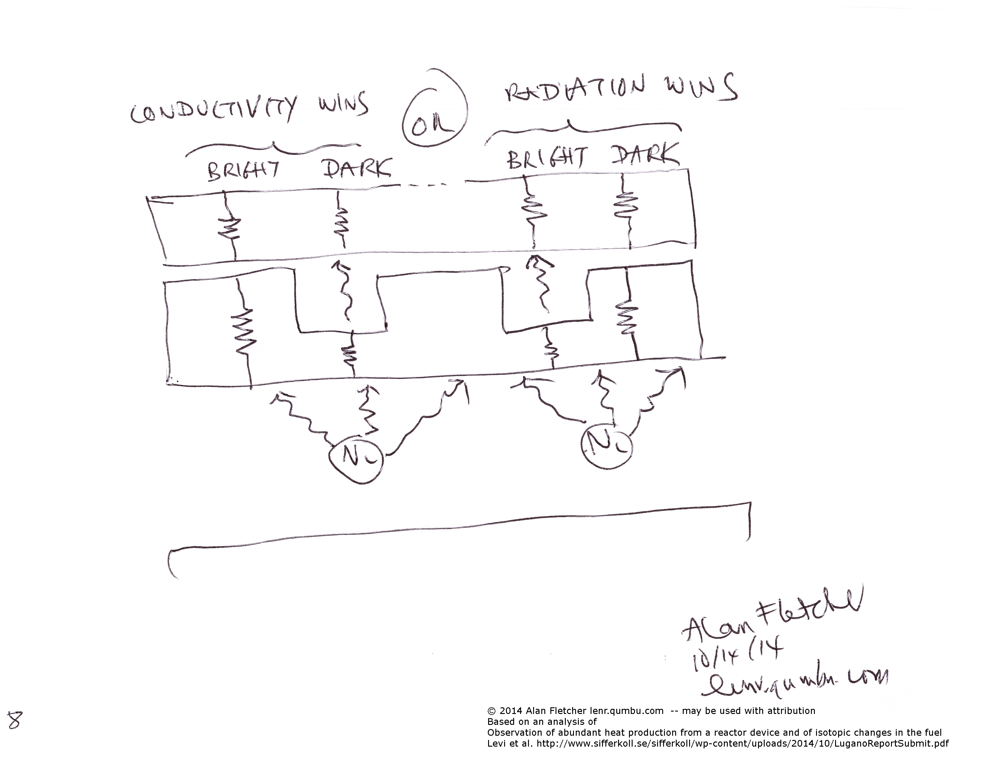
Fig 8: If the conduction through the ceramic is greater than the radiation through the gap, then the bright bands will be between the wires (left). But if radiation wins, then the bright bands could be located at the wires (right).
So without knowing the detailed internal structures, and the exact properties of the Alumina, we simply don't know.
As indicated above, I believe this analysis applies to the earlier hotcat tests, but there is probably no room for a ceramic mount in this hotcat.
An alternative construction is that the wires are embedded directly in the ceramic tube, and probably make good thermal contact with it.
In this case they might be close enough to the surface to either show as the bright bands (thermally, or by transparent radiation), or to show as dark against the brighter background of the central cavity.
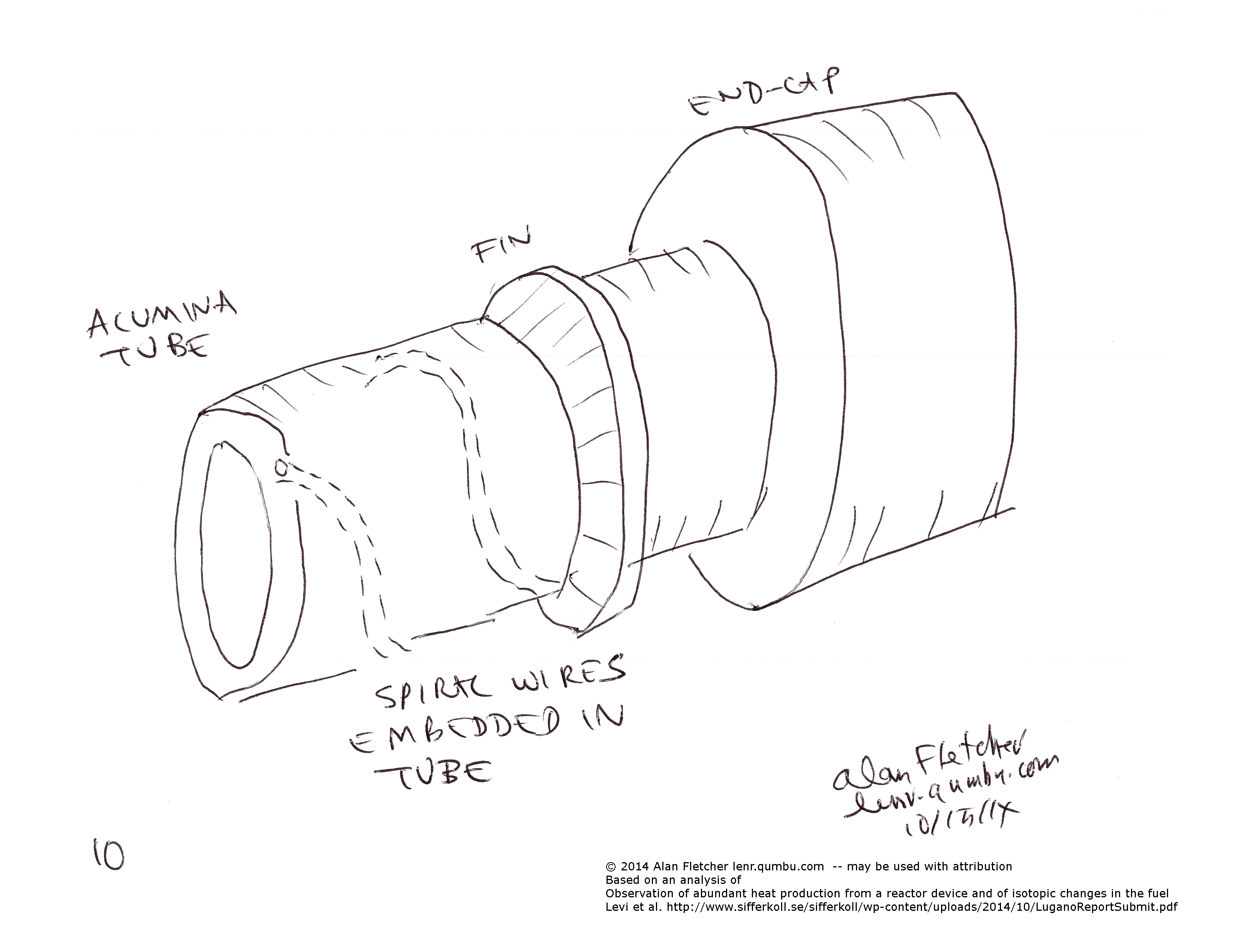
Fig 10: Wires embedded in the Alumina tube
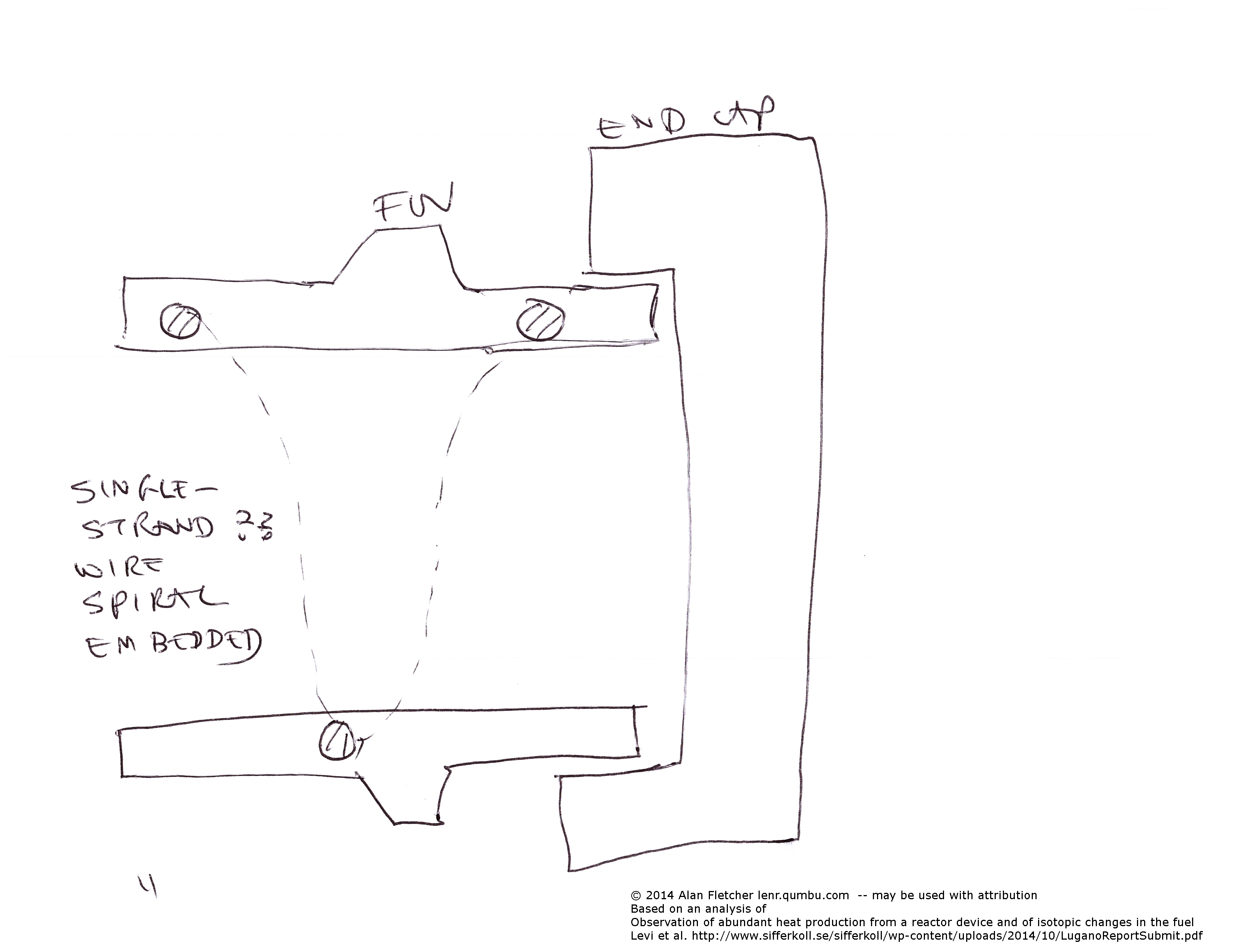
Fig 11: Wires embedded in the Alumina tube
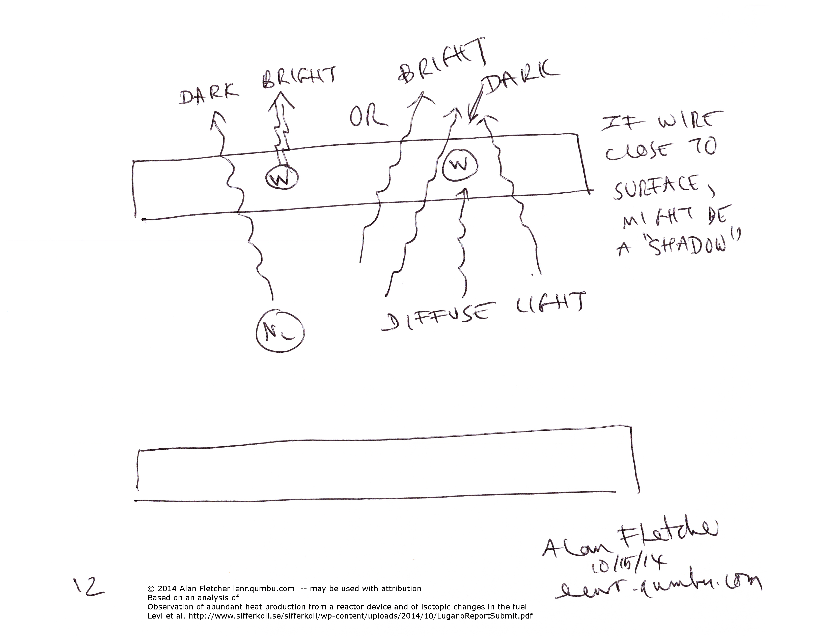
Fig 12: Wires might be brighter, or close enough to the surface to show as a "shadow" against the brighter internal source.
Bob Higgins argues on Vortex for a nested structure http://www.mail-archive.com/vortex-l@eskimo.com/msg98790.html, and says that the embedded-wire structure cannot be fabricated : http://www.mail-archive.com/vortex-l@eskimo.com/msg98799.html
However, see Structure C above for a slightly different version.